 how-to
How to Troubleshoot Legacy PLC Systems: 7-Step Guide
Table of Contents
- Before You Touch the Cabinet: Safety and Risk Assessment
- Start With Power: Supply Diagnostics on Legacy PLC Hardware
- Reading PLC Fault Codes and Diagnostic Indicators
- PLC Input and Output Troubleshooting: Modules, Wiring and Signals
- PLC Communication Troubleshooting: Serial, Ethernet/IP and the Backplane
- PLC Backup and Recovery: Firmware Flashing and Program Restoration
- When Repair Stops Making Sense: Sourcing Obsolete Parts and Migrating Data
- Frequently Asked Questions
Last Updated: October 21, 2026
Before You Touch the Cabinet: Safety and Risk Assessment
Legacy PLC troubleshooting starts before you open a cabinet door. Our first rule on any legacy PLC callout is simple: assess the risk before the fault. A programmable logic controller (PLC) runs a plant's logic scan cycle, and on aging hardware the risks multiply.
Three checks come before anything else:
- Lock out and tag out every energy source, including separate 24V supplies and any UPS feeding the rack
- Prove dead with a tested multimeter on every terminal you plan to touch
- Check arc flash boundaries and confirm your PPE rating matches the cabinet's label
Lock Out, Prove Dead, and Check Your Arc Flash Boundaries
Isolation is not a formality. Old cabinets often hide fed-back voltages from field wiring, and a "dead" terminal can still carry a signal from another source.
Arc flash risk rises with age. Corroded terminals and loose lugs create hot spots. Follow the Safe Work Australia guidance on electrical safety and your site's own isolation procedure.
Start With Power: Supply Diagnostics on Legacy PLC Hardware
Power supply failure is a common root cause on aging racks. Before chasing fault codes, confirm the supply is clean and stable.
Work through it in this order:
- Measure incoming voltage at the supply terminals, not at the wall
- Check the DC output under load, not open circuit
- Inspect for voltage fluctuations, ripple, or a sagging rail
- Look at grounding issues: loose earth straps and corroded bonds
- Swap in a known-good supply to confirm the diagnosis
A supply that reads fine unloaded can collapse the moment the I/O modules draw current, showing up as random processor faults and resets that send people down the wrong path.
Reading PLC Fault Codes and Diagnostic Indicators
PLC fault codes and diagnostic LEDs are your fastest route to the real problem, but only in context. On legacy hardware they are blunt instruments: a red RUN light tells you the processor stopped, not why.
Start with the module LEDs, then pull the fault codes from the programming software. Cross-check the code against the manual for that exact model and firmware version.
Battery Backup, Memory Corruption and Processor Faults
A dead battery backup is the quiet killer of legacy systems. When the cell fails, data registers and the program can corrupt on the next power cycle, producing a processor fault that looks like hardware failure but is really memory corruption.
Check the battery voltage on schedule, not when it fails. If you see garbled data registers or a program that won't hold, suspect the battery before the processor.
PLC Input and Output Troubleshooting: Modules, Wiring and Signals
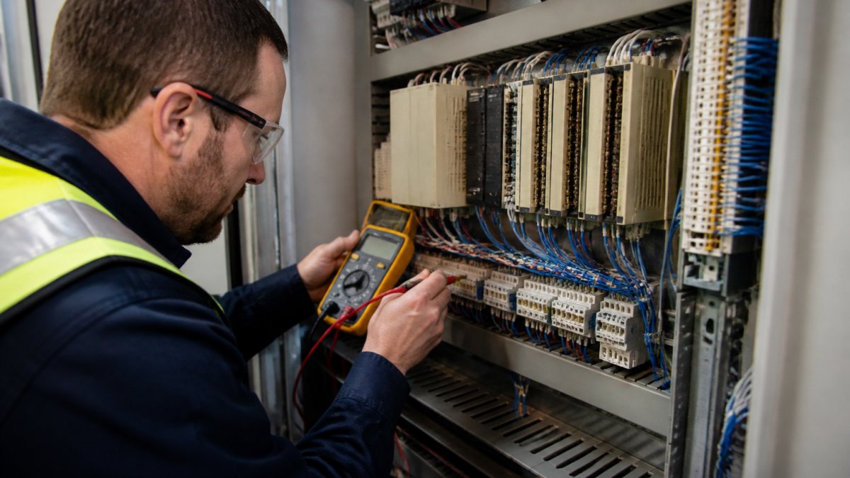
PLC input and output troubleshooting follows the signal, not guesswork. The fault is usually in the field wiring or the module, rarely the processor.
Digital Inputs: Prove the Signal at Three Points
Work the signal path from the field device back to the processor:
- At the field device, confirm the sensor or switch actually changes state. A prox sensor with a failed output will sit permanently on or off and the PLC will faithfully report a lie.
- At the terminal block, measure the voltage the input card expects. Most legacy 24V DC sinking-input cards need the input terminal pulled to 0V to register a true; sourcing cards need 24V applied. Confirm the topology before you condemn the card.
- At the module LED, force the input in software and watch the LED. If the LED follows the force but the field device does not, the fault is in the field wiring. If the LED does not follow the force, the module or backplane is suspect.
A common pattern on aging plants is a sensor that still switches but has drifted outside its rated sensing distance, working on a cold morning and missing on a hot afternoon. Intermittent inputs are usually mechanical or environmental, not electronic.
Digital Outputs: Load, Not Voltage, Tells the Truth
An output card can show correct voltage at an open terminal and still fail under load. Test with the field device connected:
- Measure voltage at the output terminal with the load energised. A reading that collapses under current points to a failing output transistor or a triac that no longer latches.
- Check the output common and return path. A loose 0V bond on the output side will make every output on the card look dead.
- For relay outputs, listen and feel for the click, then confirm continuity across the normally-open contact with the output forced on.
Analogue I/O: Scaling, Loops and Earth Loops
Analogue faults punish guesswork. A 4-20 mA loop reading 3.8 mA at the PLC but 4.0 mA at the transmitter has a wiring or earth problem, not a calibration problem.
- Confirm the loop is powered and the transmitter is in the correct 2-wire or 4-wire configuration for the card.
- Measure the current in series with a mA meter, or use a clamp, at both ends of the loop.
- Check the input card's scaling against the instrument range. A card scaled 0-20 mA against a 4-20 mA transmitter will read low across the whole span and look like drift.
Signal Interference and Separation
Signal interference from VSDs and unshielded cable is a frequent culprit on older plants, and shielded, separated runs fix more I/O faults than module swaps. Keep analogue and low-level digital cable at least 300 mm from motor and drive cable, bond shields at one end only, and check drive output cable uses the correct screened configuration.
Module and Rack-Level Checks
Before replacing a card, confirm the rack is healthy: check the backplane power rails, reseat the module, and inspect the card edge connector for corrosion. On racks that have run hot for years, oxidised connector pins mean a reseat alone clears faults that look like failing modules. Record the module part number and firmware revision before ordering, legacy I/O cards often have several incompatible revisions under one family name.
PLC Communication Troubleshooting: Serial, Ethernet/IP and the Backplane
PLC communication troubleshooting moves in layers: backplane first, then serial, then Ethernet/IP. A processor that won't talk to its I/O has a backplane problem; a rack that won't talk to the network has a protocol or cabling problem. Work the layers in order, chasing an Ethernet fault when the backplane is down wastes hours.
Backplane Faults
The backplane is the bus the processor uses to talk to its own I/O. Symptoms are specific: the processor runs but shows missing or faulted modules, or the rack faults on power-up before any network is involved.
- Check the rack power supply rails under load, not open circuit.
- Reseat the processor and the faulted module. Corroded edge connectors on hot-running legacy racks cause intermittent backplane faults that clear on a reseat and return a week later.
- Confirm the module is in the slot the program expects. On legacy systems, a card moved to a different slot during a repair will fault the rack until the configuration is corrected.
Serial Communications: RS-232 and RS-485
Serial links are where parameter drift bites hardest: the settings live at both ends and nobody records them.
- Baud rate, data bits, parity and stop bits must match at both ends. A single mismatch gives you either no communication or garbled characters, depending on how far off you are.
- Node address must be unique on the segment. Two devices at the same address will collide and both will appear intermittent.
- RS-485 termination and bias matter on long runs. Missing termination causes reflections that show up as CRC errors that increase with cable length.
An intermittent serial comms fault is almost always physical: a loose DB9 shell, a conductor that only opens when the cabinet door is closed, or a failed in-line surge protector.
Ethernet/IP and Industrial Ethernet
Ethernet faults split into physical, addressing and protocol layers.
- Physical, check link LEDs at both ends, swap the patch lead, and confirm the cable is industrial-rated rather than office-grade. Vibration and heat kill office cable in a cabinet.
- Addressing, confirm IP address, subnet mask and gateway match the design. Duplicate IP addresses are a classic legacy-plant fault after a contractor clones a configuration.
- Protocol, confirm the device is in the correct mode (for example, a remote I/O adapter expecting a specific scanner connection), and check that the connection size and RPI settings in the scanner match the adapter's capability.
Communication Parameter Settings Drift
Check communication parameter settings against the original design. Baud rate, node address and IP settings drift as people swap parts, and one mismatch takes the whole link down. Keep a written record of every device's settings inside the cabinet door, on legacy systems it is often the only reliable source once the original integrator has left.
Cable and Connection Integrity
Then verify cable and connection integrity: bent pins, cracked insulation, loose connectors. Use a cable tester on suspect runs rather than swapping cables at random, and inspect connectors under bright light, a single bent pin on a DB9 or RJ45 mimics a software fault.
PLC Backup and Recovery: Firmware Flashing and Program Restoration
PLC backup and recovery is your insurance policy, and it must exist before the fault. If you have no current backup, take one now, before any repair.
The recovery sequence:
- Back up the current program and data registers, even if faulty
- Flash the firmware only with the correct file for that hardware revision
- Restore the program and verify the logic scan cycle runs clean
- Test I/O against the restored program before handback
Firmware flashing on legacy hardware is unforgiving. The wrong file bricks the processor. Confirm the part number and revision, and never flash during a production window.
When Repair Stops Making Sense: Sourcing Obsolete Parts and Migrating Data
Hardware obsolescence forces a decision: keep patching, or plan the exit. Sourcing obsolete spare parts gets harder and dearer every year, and second-hand modules carry unknown history.
Two angles most guides skip matter here:
Interfacing Legacy PLCs With Modern IIoT Gateways
You can bridge old and new without a full rip-out: IIoT gateways read data from legacy protocols and push it to modern systems, buying visibility while you plan migration.
Cybersecurity Risks of Legacy Hardware
Legacy hardware predates modern threats.
Data migration from legacy to modern systems is the strategic play.
That's where a specialist helps. Industry Power Solutions works with legacy equipment, from PLC programming to system integration, and plans migration around your production, not against it.
Legacy PLC systems don't have to mean constant downtime. The plants that stay running have a clear troubleshooting process, current backups and a plan for obsolescence.
Frequently Asked Questions
What are the most common faults in legacy PLC systems?
Power supply failure tops the list, usually from voltage fluctuations or aging capacitors. Next come I/O module faults caused by signal interference, grounding issues or worn field wiring. Processor faults from a flat battery backup and memory corruption are also common on older units, along with communication dropouts on serial links. Most of these show up first as diagnostic LEDs or fault codes, so check those before pulling modules. Regular preventive maintenance, including battery replacement and thermography on supply terminals, catches a good share of them early.
How do you diagnose a PLC input or output problem?
Work from the field device back to the module. Confirm the sensor or actuator is actually switching, then check voltage at the field wiring terminals. If the signal reaches the terminal but the diagnostic LED on the module stays dark, the module is the likely fault. If the LED lights but the logic does not respond, inspect the ladder logic and data registers for that address. Swapping a suspect module into a spare slot is a quick way to confirm, but record the original addressing first so you can restore it.
What should you check when a PLC stops communicating with other equipment?
Start with the physical layer: cable integrity, connector seating and termination resistors on serial networks. Then confirm communication parameters such as baud rate, parity and node address match on both ends, because a single changed setting after a module swap will kill the link. For Ethernet/IP, check switch port status and IP addressing. Signal interference from nearby drives or poor grounding also causes intermittent dropouts. If the backplane is involved, reseat the modules and check for bent pins before assuming the processor is faulty.
When should you repair or replace a legacy PLC instead of troubleshooting further?
Replace when spares are no longer sourceable, when the programming software only runs on an operating system you can no longer support, or when downtime from repeat faults costs more than a migration. A practical test is whether you can still take a full backup and restore it. If you cannot, you have no recovery path and the risk is unacceptable. Get a documented condition assessment and a staged migration plan, so production keeps running while the new system is proven.